Signalverarbeitung
Home /
Science & Education
/
Science - Electronic
/ Signalverarbeitung
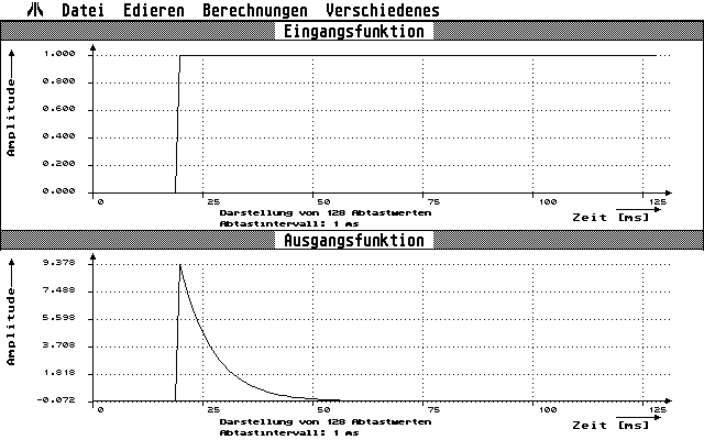
Circuit simulator for digital filters from the FH Berlin Telecom. A circuit can be entered via block diagram in a comfortable editor and then simulated. A graphical output of any response function (e.g. step response) or the Bode diagram is generated. A sampling circuit can consist of the components input and output (only 1 x each), delay unit, adder with a maximum of 3 inputs, multiplier with a maximum of 3 inputs or a constant and look-up table with one input.